 Guest
Guest
Adsorbed water is the water layer formed around the soil particle especially in the case of fine-grained soils. This reduces the size of the void space by about 10%. Hence, permeability reduces.
Chapter:
permeability-of-soil
1. Explain methods for determining coefficient of permeability of soil.
The coefficient of permeability can be determined by the following methods:
i) Laboratory methods
- Constant head permeability test
- Variable head permeability test
ii) Field methods
- Pumping-out tests
- Pumping-in tests (bore hole tests)
Constant head permeability test:
This test is more suited for coarse grained soil such as gravel, coarse & medium sand.
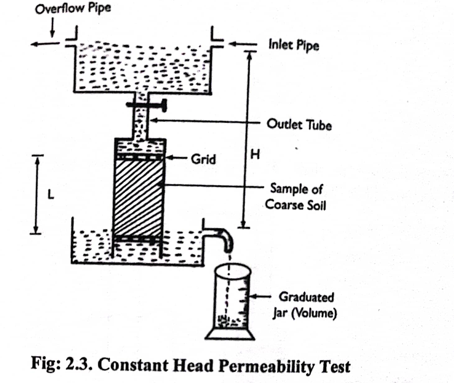
Above figure shows a constant head permeameter that consists of a vertical tube (cylinder) containing soil sample. The diameter and height of the cylinder (permeameter or tube) can be of any convenient dimensions. The constant level of water is maintained in a small water tank by providing over flow tube.
Procedures:
1. A permeameter or cylinder is cleaned and dried.
2. Coarse grained soil sample which is to be tested is placed in cylinder.
3. Vertical cylinder containing soil sample is provided with top & bottom grids (screen, pores plate) as shown in fig: 2.3.
4. Smaller water tank is attached with cylinder with the help of vertical tube (outlet tube) as shown in above figure.
5. Water is allowed to pass through soil sample and water after passing through soil sample in a particular time, t is collected in a graduated jar from where quantity of seepage water in terms of volume is measured.
6. With the help of Darcy's law coefficient of permeability of coarse grained soil is calculated as below:
`q=k*i*A`
or, `k=q/(i*A)`
Where, `q` is the discharge per unit time
`A=`Area of cross section of soil sample
`i=`Hydraulic gradient
`i=H/L`
Thus,
`k=(Q/t)/((H/L)**A)`
or, `k=(QL)/(H A t)=(qL)/(A H)`
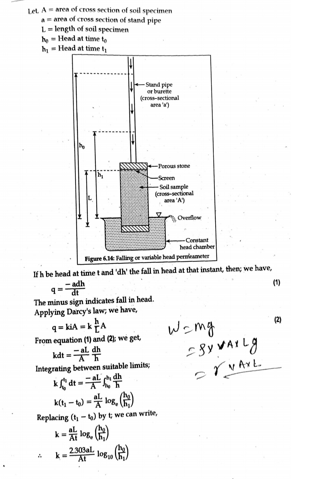
Falling head permeability test:
Falling head permeability test is more suited for fine grained soil such as silt and clay.
Above figure shows a following head permeameter which consists of a vertical cylinder (Permeameter) of c/s area, A. A transparent stand pipe of c/s area, a is attached to the test cylinder. The test cylinder is kept in a container filled with water.
Procedures
1. Permeameter (cylinder) is cleaned and dried.
2. The fine grained soil sample is placed in side cylinder and then two screen (grids) are fitted as shown in fig: 2.4.
3. A transparent stand pipe is connected with cylinder at top.
4. Before the commencement of test the soil sample is saturated by allowing the water to flow continuously through the sample from the stand pipe.
5. After the saturation is completed, the stand pipe is filled with water upto a height of and a stop watch is started. Let initial time be `t_1`
6. The time, `t_2` when the water level drops from `h_1` to `h_2` is noted.
7. The coefficient of permeability of soil sample is found out by following calculations:
FIELD METHODS :
1. Pumping out tests:
The tests can be conducted in both unconfined and confined aquifer. An aquifer is a water bearing stratum in natural ground formations. If it overlies an impervious stratum and the water table is free to fluctuate, it is called unconfined aquifer. On the other hand, if the aquifer is bound by impervious strata both at top and bottom, it is called confined aquifer.
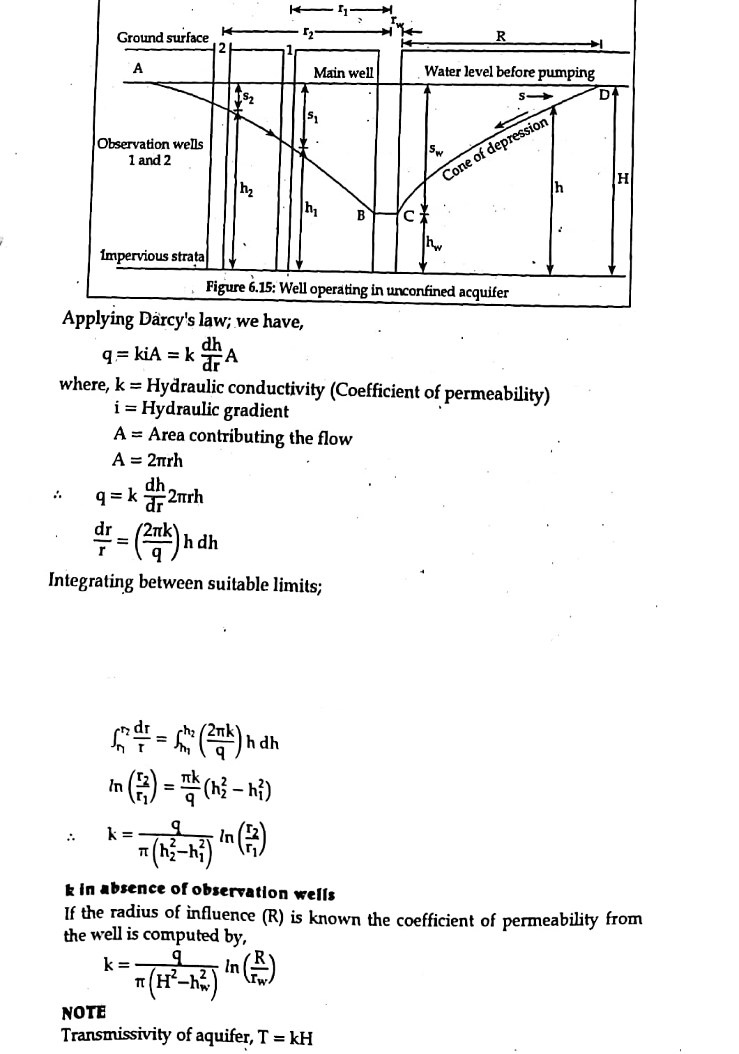
1.1 Pumping out test in unconfined aquifer
Figure below is a schematic diagram illustrating pumping out test in an unconfined aquifer.
Let `r_w` = Radius of main well
`R` = Radius of zero drawdown as maximum radius of influence
`h_w` = Depth of water in the main well, during pumping, measured above impervious layer
`H` = Height of initial water level above imperious layer
`q` = Rate at which water is pumped out of well.
Two observation wells are driven at `r_1` and `r_2` distance from the center of main well. Pumping is adjusted that the rate of pumping is equal to the rate of yield. At the observation wells `S_1` and `S_2` are the drawdown located at `r_1` and `r_2` distance away from the main well.
`h_1` and `h_2` are the water levels in two observation wells located at `r_1` and `r_2` distance away from the main well.
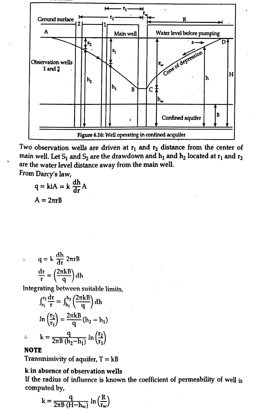
1.2. Pumping out test in confined aquifer
The figure 6.16 is a schematic diagram illustrating pumping out test in the confined aquifer.
Let, `q=`Discharge or rate at which water is pumped out of main well
`r_w`= Radius of main well
`R `= Maximum radius of influence
`h` = Depth of water in well, measured above bottom impervious stratum, during pumping.
`B` = Height of initial piezometric surface above bottom impervious stratum
2. Pumping in tests
2.1) Open end tests
An open end pipe is sunk in the strata and the soil is taken out of the pipe just to the bottom. Clean water, having température slightly higher than the ground water, is added through a metering system to maintain gravity flow under constant head. The permeability is calculated from the following expression,
`k = q/(5.5rh)`
where, h = differential head of water
r = Radius of casing
q= Constant rate of flow
2.2) Packer tests
An uncased portion of the drill hole or a perforated portion of the casing is used for performing the test. In case the test is performed during drilling a top packer is placed just inside or below the casing. Water is pumped in the lower portion of the hole. The length of the packer on expansion should be five times the diameter of hole. Testing is started from the bottom of the hole and continued upwards. Coefficient of permeability is determined from the following expression:
`k = q/(2pi*Lh) * log_10(L/r); L >= 10r`
`k = q/(2pi*Lh) * sin h ^ - 1 * L/(2r); 10r > L >= r`
where, L is the length of portion of hole tested.
2. Explain Factors affecting permeability of soil,
Permeability is a property of soil by virtue of which the soil mass allows water (or any other fluid) to flow through it.
The expression for coefficient permeability which is derived from the comparison of poiseuille’s law with Darcy’s law.
`k=C**D^2**e^3/(1+e)**gamma_w/mu`
Where k = Coefficient of permeability
C = Shape constant
D = Effective grain size
e = Void ratio
`gamma_w=` Unit weight of water
`mu`=Dynamic Viscosity of water
Following are factors effecting permeability of soils.
- Size of soil particle
- Specific Surface Area of Soil Particle
- Shape of soil particle
- Void ratio
- Soil structure
- Degree of saturation
- Water properties
- Temperature
- Adsorbed water
- Organic Matter
1) Size of particles
The permeability varies approximately as the square of the grain size. Relationship is
`k=C**D^2**e^3/(1+e)**gamma_w/mu`
`D` is the effective diameter of the soil particles in cm.
From the above equation we can say, the permeability of soil is directly proportional to the square root of the particle diameter. If the soil particle is large then permeability will be high, and if the soil particle is small then permeability will be less.
This happens because the large particle contain large volume of voids, and other hands small particle contain small volume of voids. Hence, the flow of water through soil mass will be more in case large particle.
2. Specific Surface Area of Particles
Specific surface area of soil particles also effects the permeability. Higher the specific surface area lower will be the permeability.
`k prop 1/( s p r c i f i c \ S u r f a c e \ A r e a)`
3. Shape of Soil Particle
Rounded Particles will have more permeability than angular shaped. It is due to specific surface area of angular particles is more compared to rounded particles.
4. Void Ratio
In general, Permeability increases with void ratio. But it is not applicable to all types of soils. For example, Clay has high void ratio than any other types of soil but permeability for clays is very low. This is due to, the flow path through voids in case of clays is extremely small such that water cannot permit through this path easily.
The relation between coefficient of permeability and void ratio can be expressed from equation (1) as
For Clay
`k prop (C e^3)/(1+e)`
Where, C = Shape of the flow path,
e = Void ratio.
For coarse grained soil, “C” can be neglected. Hence
`k prop e^3/(1+e)`
5. Soil Structure
The permeability may vary with different geometric arrangement and shape of voids.If the particles are arranged in a flocculated structure, then the permeability will be low. On the other hand, if the particles are arranged in a dispersed structure, then permeability will be high.
Permeability of soil also depends on the structural defects like crack.
6. Degree of Saturation
Partially saturated soil contain air voids which are formed due to entrapped air or gas released from the percolating fluid or water. This air will block the flow path thereby reduces the permeability. Fully saturated soil is more permeable than partially saturated soil.
7. Water Properties
Various properties of water or fluid such as unit weight and viscosity also effects the permeability. However, unit weight of water will not affect much since it does not change much with temperature.
But when temperature is increased viscosity decreases rapidly. From equation (1), permeability increase when viscosity decreases.
`k prop gamma_w/mu`
8. Temperature
Temperature also affects the permeability in soils. From equation (1), permeability is inversely proportional to the viscosity of the fluid. It is known that viscosity varies inversely to the temperature. Hence, Permeability is directly related to temperature.
Greater the temperature, higher will be the permeability. That is the reason, seepage is more in summer seasons than in winter.
`k prop 1/mu prop` temperature.
9. Adsorbed Water
10. Organic matter
Presence of organic matter decreases the permeability. This is due to blockage of voids by the organic matter.
All Chapters
View all Chapter and number of question available From each chapter from Geotechnical-Engineering-Subjective
Topics
This Chapter permeability-of-soil consists of the following topics
