 Guest
Guest
Chapter:
1. Design and detail a tension splice to connect `300\ mm**12\ mm` flat with `300\ mm ** 16\ mm` flat using two cover plates to carry a tension of `400\ KN`. Use M20 high strength bolt of property class `8.8` if - no slip is permitted at ultimate load
- slip is permitted at ultimate load
Solution:
For M20 bolts of class 8.8,
`d=20 mm`
`d_0=20+2=22\ mm`
`f_(ub)=800 MPa`
`f_(yb)=640 MPa`
Also, Given,
`f_y=250 MPa` and `f_u=410\ MPa`
When no slip is permitted at the ultimate load
Nominal shear capacity of bolt is,
`V_(n s f)=mu_f n_eK_h gamma_(m f) F_0`
Where,
`mu_f=0.55` is the slip factor.
`n_e` is the number of effective interfaces offering frictional resistance to slip.
`K_h=1.0` is the clearances hole
`gamma_(mf)=1.25`
`F_0=A_b b F_0=0.78**(pi d^2)/4&&0.70=137.225\ KN` is the proof load.
thus, `V_(n s f)=0.55**1**1**137.225=75.471\ KN`
Thus, `V_(d s f)=75.379/1.25=60.379\ KN`
Now, the number of bolts is,
`n=400/60.379=6.625~=7`
Slip is permitted at ultimate load:
`gamma_(mf)=1.1`
`V_(d s f)=15.471/1.1=68.6\ KN`
Thus, the number of bolts is, `=400/68.6=5.831~=6`
The Design shearing strength of bolts is,
`V_(dsb)=V_(nsb)/gamma_(mb)`
`=(f_(ub)/(root()(3) gamma_(mb)))(n_n*A_(nb)+n_s*A_(sb))`
`=206.628\ KN`
Again, the design bearing shear strength of a single bolt is,
`V_(dpb)=(2.5 K_b d tf_u)/gamma_(mb)`
Where, `K_b` is the smaller value of `e/(3d_0)`, `p/(3d_0)-0.25`, `f_(ub)/f_u`, and `1`
let `e=40\ mm>1.5d_0` and `p=100 mm >2.5d`
Here, `e/(3d_0)=40/(3**22)=0.606`
`p/(3d_0)-0.25=100/(3**22)-0.25=1.265`
`f_(ub)/f_u=800/410=1.951`
Thus, `K_b=0.606`
Hence, the design bearing shear strength of a single bolt is,
`V_(dpb)=(2.5**0.606**20**12**410)/1.25`
`=119260.8 N`
`=119.260\ KN`
Thus, the design strength of a single bolt is `119.260\ KN`
The design strength of the connection of 6 bolts is `6**119.260=715.564\ KN`
Check for plates:
`T_(dg)=(f_yA_g)/gamma_(m0)=818.182>715.566\ KN`
Also, `T_(dn)=(0.9 f_u A_n)/gamma_(m1)`
`=906.854>715.566\ KN`
Again, for the design strength due to block shear,
`A_(vg)=2**(40+2**100)**12=5760\ mm^2`
`A_(vn)=2**(40+2**100-2.5**22)**12=4440\ mm^2`
`A_(tg)=2**50**12=1200\ mm^2`
`A_(tn)=(50-22/2)**2**12=936\ mm^2`
Now,
`T_(db1)=[(A_(vg)*f_y)/(root()(3)**gamma_(m0))+(0.9**A_(tn)**f_u)/gamma_(m1)]`
`=1032.111\ KN`
Also, `T_(db2)=[(0.9**A_(vn)**f_u)/(root()(3)**gamma_(m1))+(A_(tg)**f_y)/gamma_(m0)]`
`=1029.453\ KN`
Thus, `T_(db)=1029.453\ KN > 715.566\ KN`
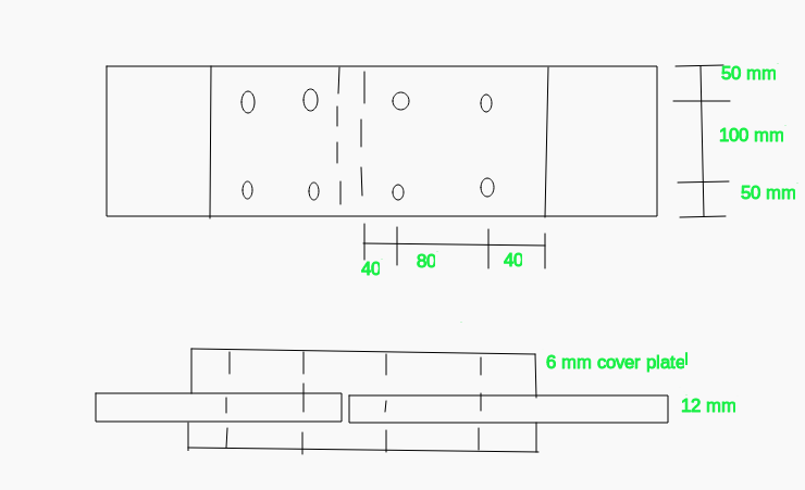
2. Two 12 mm thick steel flats are spliced by two 6 mm thick plates with four M16 bolts of product grade C and property class `4.6` as shown below. Determine ultimate load carrying capacity of connection. `f_y=250 MPa` and `f_u=410\ MPa`.
Solution:
For M16 bolts of class 4.6,
`d=16 mm`
`d_0=16+2=18mm`
`f_(ub)=400 MPa`
`f_(yb)=240 MPa`
Also, Given,
`f_y=250 MPa` and `f_u=410\ MPa`
The Design shearing strength of bolts is,
`V_(dsb)=V_(nsb)/gamma_(mb)`
`=(f_(ub)/(root()(3) gamma_(mb)))(n_n*A_(nb)+n_s*A_(sb))`
Here,
`n_n=1`
`n_s=1`
Now, `A_s=(pi d^2)/4=(pi*16^2)/4=201.06\ mm^2`
And, `A_n=0.78**201.06=156.82\ mm^2`
Thus,
`V_(dsb)=400/(root()(3)**1.25)**(156.82+201.06)`
`=66119\ N`
`=66.119\ KN`
Again, the design bearing shear strength of a single bolt is,
`V_(dpb)=(2.5 K_b d tf_u)/gamma_(mb)`
Where, `K_b` is the smaller value of `e/(3d_0)`, `p/(3d_0)-0.25`, `f_(ub)/f_u`, and `1`
Here, `e/(3d_0)=40/(3**18)=0.7407`
`p/(3d_0)-0.25=80/(3**18)-0.25=1.23`
`f_(ub)/f_u=400/410=0.975`
Thus, `K_b=0.7407`
Hence, the design bearing shear strength of a single bolt is,
`V_(dpb)=(2.5**0.7407**16**12**410)/1.25`
`=116615.8 N`
`=116.6\ KN`
Thus, the design strength of a single bolt is `66.119\ KN`
The design strength of the connection of 4 bolts is `4**66.119=264.476\ KN`
Now, the design strength of plates governed by rupture is given by,
`T_(dn)=(0.9 f_u A_n)/gamma_(m1)`
`=(0.9**410**(200-2**18)**12)/1.25`
`=580953\ N`
`=580.953\ KN`
Again, for the design strength due to block shear,
`A_(vg)=2(40+80)**12=2880\ mm^2`
`A_(vn)=2(40+80-18-18/2)=2232\ mm^2`
`A_(tg)=(100**12)=1200\ mm^2`
`A_(tn)=(100-18/2-18/2)=984\ mm^2`
Now,
`T_(db1)=[(2880**250)/(root()(3)**1.1)+(0.9**984**410)/1.25]`
`=668.379\ KN`
Also, `T_(db2)=[(0.9**2232**410)/(root()(3)**1.25)+(1200**250)/1.10]`
`=653.136\ KN`
Thus, `T_(db)=653.136\ KN`
Thus, the ultimate design load carrying capacity of the connection is `264.484\ KN`
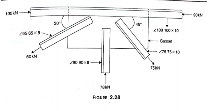
3. Design a welded connection for member at a joint of truss shown in figure below. `f_y=250\ MPa` and `f_u=410\ MPa`. The forces shown are at services load.
Solution:
From Steel table, We have,
For `<100100**10`, `C_(x x)=28.4\ mm=C_(y y)`
For `<9090**8`, `C_(x x)=25.1\ mm=C_(y y)`
For `<7575**10`, `C_(x x)=21.00\ mm=C_(y y)`
For `<6565**8`, `C_(x x)=18.9\ mm=C_(y y)`
For the design of member carrying `50\ KN` tension load,
Design load `=1.5**50=75\ KN`
`S_(m i n)=3\ mm`
Considering only the side weld, `S_(m a x)=3/4**8=6\ mm`
Let the size of the fillet weld id `5\ mm`
Now, the effective throat thickness, `t_t=KS=0.7**5=3.5\ mm`
Let, `l_1` and `l_2` be the length of the weld along the back face and toe face and let the given tension is balanced by the strength weld provided at toe and back face of angle section `F_1` and `F_2` at back and toe face of given angle section. Then,
`F_1=l_1**t_t**f_(wd)`
Where, `f_(wd)=f_u/(root()(3)**gamma_(MW))=189.371\ MPa` is the strength of the fillet weld.
`F_2=l_2**t_t**f_(wd)`
Now, `l_1t_1f_(wd)+l_2t_2 f_(wd)=P(N)`
or, `l_1+l_2=P/(t_t**f_(wd))`.....(i)
Taking moment at the centre of gravity of section,
`l_1t_1f_(wd)**C_(x x)=l_2t_2 f_(wd)**(b-C_(x x))`
`l_1=(l_2(b-C_(x x)))/(C_(x x))` .....(ii)
Now, Solving the equations (i) and (ii), we get,
`l_2=P/(t_t**f_(wd))**C_(x x)/b`
`l_1=P/(t_t**f_(wd))**(b-C_(x x))/b`
Thus, `l_1=32.902\ mm` and `l_2=80.254\ mm`
Now,
The actual `l_1=32.902+2**3.5=40\ mm`
The actual `l_2=80.254+2**3.5=87.254\ mm~=90\ mm`
Thus, provide the size of fillet weld `5\ mm` and length of weld along toe side and along back side `40\ mm` and `90\ mm` respectively.
Design of Member carrying Compressive load,

Solution:
From Steel table, We have,
For `<100100**10`, `C_(x x)=28.4\ mm=C_(y y)`
For `<9090**8`, `C_(x x)=25.1\ mm=C_(y y)`
For `<7575**10`, `C_(x x)=21.00\ mm=C_(y y)`
For `<6565**8`, `C_(x x)=18.9\ mm=C_(y y)`
For the design of member carrying `50\ KN` tension load,
Design load `=1.5**50=75\ KN`
`S_(m i n)=3\ mm`
Considering only the side weld, `S_(m a x)=3/4**8=6\ mm`
Let the size of the fillet weld id `5\ mm`
Now, the effective throat thickness, `t_t=KS=0.7**5=3.5\ mm`
Let, `l_1` and `l_2` be the length of the weld along the back face and toe face and let the given tension is balanced by the strength weld provided at toe and back face of angle section `F_1` and `F_2` at back and toe face of given angle section. Then,
`F_1=l_1**t_t**f_(wd)`
Where, `f_(wd)=f_u/(root()(3)**gamma_(MW))=189.371\ MPa` is the strength of the fillet weld.
`F_2=l_2**t_t**f_(wd)`
Now, `l_1t_1f_(wd)+l_2t_2 f_(wd)=P(N)`
or, `l_1+l_2=P/(t_t**f_(wd))`.....(i)
Taking moment at the centre of gravity of section,
`l_1t_1f_(wd)**C_(x x)=l_2t_2 f_(wd)**(b-C_(x x))`
`l_1=(l_2(b-C_(x x)))/(C_(x x))` .....(ii)
Now, Solving the equations (i) and (ii), we get,
`l_2=P/(t_t**f_(wd))**C_(x x)/b`
`l_1=P/(t_t**f_(wd))**(b-C_(x x))/b`
Thus, `l_1=32.902\ mm` and `l_2=80.254\ mm`
Now,
The actual `l_1=32.902+2**3.5=40\ mm`
The actual `l_2=80.254+2**3.5=87.254\ mm~=90\ mm`
Thus, provide the size of fillet weld `5\ mm` and length of weld along toe side and along back side `40\ mm` and `90\ mm` respectively.
Design of Member carrying `78**1.5=117\ KN` Compressive load,
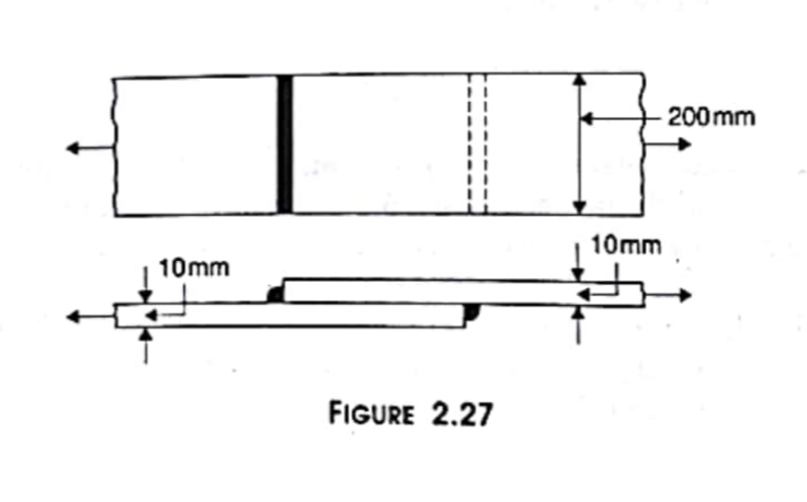
4. Determine size of fillet welds needed for strength of plates in tension. `f_y=250\ MPa` and `f_u=410\ MPa`
Solution:
Here, the thickness of both plates is same. So, the size of welds is also same.
We know, the design strength of fillet weld is,
`f_(wd)=f_u/(root()(3)**gamma_(mw))`
`=410/(root()(3)**1.25)`
`=189.371\ MPa`
We Know, the minimum size of the weld is, `S_(m i n)=5\ mm` and the maximum size of the weld is weld is `S_(m a x)=10-1.5=8.5\ mm`
Now,
`S` is the average of the minimum and maximum value. i.e, `S=6.75~=7\ mm`
Hence, the size of the fillet weld is `7\ mm`
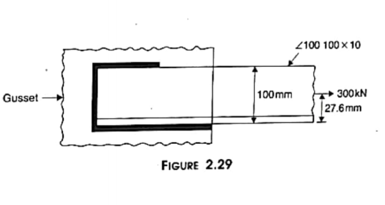
5. Find length of fillet welds shown in figure below to connect `<100100**10` to a gusset of `12\ mm` thickness. `f_y=250\ MPa` and `f_u=410\ MPa`
Solution:
`f_(wd)=f_u/(root()(3)**gamma_(MW))=189.371\ MPa`
`S_(m i n)=5\ mm`
`S_(m a x)` at side `=3/4**t=7.5\ mm`
We know, `S_(m a x)` at end side `=8.5\ mm`
Let, `S` be the average of the `S_(m i n)`, `S_(m a x)` and `S_(m a x)`
Thus, `S=7\ mm`
Effective throat thickness is, `t_t=4.9\ mm`
Let `l_e` be the effective length of weld, them
`F_(wd)=f_(wd)**A_e=f_(wd)**l_e**t_t`
or, `l_w=F_(wd)/(f_(wd)**t_t)=323.304\ mm`
The welding is provided here at the side and end edge and the length of weld along end edge is `100\ mm`. Let `l_1` and `l_2` be the length of the weld at toe and back of angle section, then the strength of the weld at end is `=100**4.9**189.371=92791.790\ N`
Strength of weld at the side is `207208.210\ N`. Thus,
`l_1**t_t**f_(wd)+l_2**t_t**f_(wd)=207208.210`
or, `l_1+l_2=223.304`.....(i)
Taking moment at the centre of gravity of the section, we get,
`l_1**27.6=l_2**72.4`
or, `l_1=2.623 l_2`....(ii)
Now, solving (i) and (ii), we get,
`l_1=61.636\ mm` and `l_2=161.669\ mm`
But, the actual `l_1=61.636+2**4.9=71.436~=75\ mm`
Actual `l_2=161.669+2**4.9=171.469~=175\ mm`
Thus, the length of fillet weld is, `=100+175+75=350\ mm`
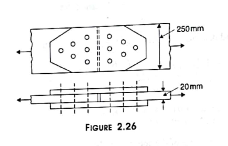
6. Determine ultimate bearing capacity of connection shown below in tension. M20 bolts of grade C and property class 5.6 are used. Also, find thickness of cover plate. `f_y=250\ MPa` and `f_u=410\ MPa`.
Solution:
For M20 bolts of class 5.6,
`d=20 mm`
`d_0=20+2=22\ mm`
`f_(ub)=500 MPa`
`f_(yb)=300 MPa`
Also, Given,
`f_y=250 MPa` and `f_u=410\ MPa`
The Design shearing strength of bolts is,
`V_(dsb)=V_(nsb)/gamma_(mb)`
`=(f_(ub)/(root()(3) gamma_(mb)))(n_n*A_(nb)+n_s*A_(sb))`
Here,
`n_n=1`
`n_s=1`
Now, `A_s=(pi d^2)/4=(pi*20^2)/4=314.15\ mm^2`
And, `A_n=0.78**314.15=245.044\ mm^2`
Thus,
`V_(dsb)=500/(root()(3)**1.25)**(245.044+314.15)`
`=129140\ N`
`=129.140\ KN`
Again, the design bearing shear strength of a single bolt is,
`V_(dpb)=(2.5 K_b d tf_u)/gamma_(mb)`
Where, `K_b` is the smaller value of `e/(3d_0)`, `p/(3d_0)-0.25`, `f_(ub)/f_u`, and `1`
Let `e=40 mm > 1.5d_0` and `p=60 mm >2.5 d`.
Here, `e/(3d_0)=40/(3**22)=0.6060`
`p/(3d_0)-0.25=60/(3**22)-0.25=0.6590`
`f_(ub)/f_u=500/410=1.219`
Thus, `K_b=0.6060`
Hence, the design bearing shear strength of a single bolt is,
`V_(dpb)=(2.5**0.6060**20**20**410)/1.25`
`=198768 N`
`=198.768\ KN`
Thus, the design strength of a single bolt is `129.140\ KN`
The design strength of the connection of 6 bolts is `6**129.140=774.84\ KN`
Now, the design strength of plates governed by rupture is given by,
`T_(dn)=(0.9 f_u A_n)/gamma_(m1)`
`=(0.9**410**(250-1**22)**20)/1.25`
`=1346112\ N`
`=1346.112\ KN`
